FOBOS Focal-Plane Layout
To show the layout of the active FOBOS apertures during a specific setting of
the spectrographs, use the fobos_layout script:
$ fobos_layout -h
usage: fobos_layout [-h] [--mode [MODE ...]] [--design DESIGN]

Show FOBOS aperture deployment for a given mode

optional arguments:
  -h, --help         show this help message and exit
  --mode [MODE ...]  FOBOS spectrograph mode(s). Can be a single integer,
                     defining a single mode for all spectrographs, or a set of
                     three integers that set the mode for each spectrograph
                     individually. Spectrograph modes are: (1) single-fiber
                     apertures, (2) 37-fiber IFUs, (3) monolithic IFU. (default:
                     1)
  --design DESIGN    Focal-plane layout design. Currently testing two designs.
                     One where the spectrograph-to-module mapping distributes
                     all three spectrographs over the full FOBOS field-of-view
                     (design 1) and one where the modules for a given
                     spectrograph are confined to a coherent region in the focal
                     plane. (default: 1)
Example
If you run fobos_layout without any arguments, it will show the following plot:
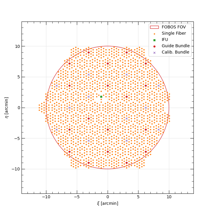
Default on-sky layout of FOBOS apertures relative to the field center. The circular FOV of the Keck II Nasmyth port is large red circle. Each marker represents an active Starbug in the focal plane and the marker shape and color represents they Starbug payload type: single-fiber apertures are orange dots, 37-fiber IFUs are green squares, imaging bundles used for guiding and focus-tracking are small red circles, and 7-fiber flux-calibration bundles are purple crosses. Note the monolithic IFU is located at the right edge of the field of view, where there appears to be a missing Starbug module.
Spectrograph Modes
Each spectrograph can be set to one of three modes:
MOS: Deploys mostly single-fiber apertures (cf. Spectrograph 1),
IFU: Deploys 37-fiber IFUs and sky fibers, and
MONO: Deploys the monolithic IFU and sky fibers.
You can use the fobos_layout script to show the apertures deployed for these
options and any combination of modes; e.g., --mode 1 2 1 sets spectrographs
1 and 3 in MOS mode and spectrograph 2 in IFU mode.
The table(s) below provide the number of apertures of each type deployed in each mode for each spectrograph. Note that the only difference between the three spectrographs is that Spectrograph 1 deploys one 37-fiber IFU in MOS mode. This to enable one IFU to always be on-sky in any mode for quick follow-up of targets of opportunity.
Spectrograph 1
Payload |
MOS |
IFU |
MONO |
|---|---|---|---|
Designated Sky |
4 |
56 |
27 |
Single-Fiber |
533 |
0 |
0 |
37-fiber IFU |
1 |
14 |
0 |
7-fiber Flux Cal. IFU |
4 |
4 |
4 |
547-fiber Mono IFU |
0 |
0 |
1 |
Total Fibers |
602 |
602 |
602 |
Spectrograph 2
Payload |
MOS |
IFU |
MONO |
|---|---|---|---|
Designated Sky |
0 |
56 |
27 |
Single-Fiber |
546 |
0 |
0 |
37-fiber IFU |
0 |
14 |
0 |
7-fiber Flux Cal. IFU |
4 |
4 |
4 |
547-fiber Mono IFU |
0 |
0 |
1 |
Total Fibers |
574 |
602 |
602 |
Spectrograph 3
Payload |
MOS |
IFU |
MONO |
|---|---|---|---|
Designated Sky |
0 |
56 |
27 |
Single-Fiber |
546 |
0 |
0 |
37-fiber IFU |
0 |
14 |
0 |
7-fiber Flux Cal. IFU |
4 |
4 |
4 |
547-fiber Mono IFU |
0 |
0 |
1 |
Total Fibers |
574 |
602 |
602 |
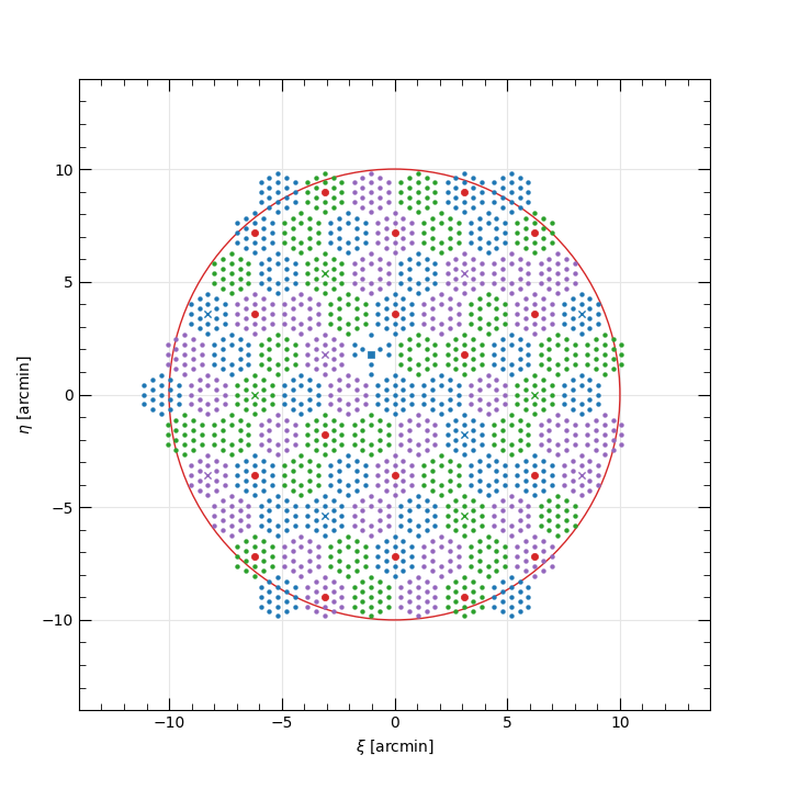
Design options
The producer.deploy.FOBOSApertures class allows for two different
spectrograph-to-module mapping design options, numbered 1 and 2. All scripts
currently use the first option, which maps modules in a way that each
spectrograph samples regions distributed over the full field of view. When all
spectrographs are in MOS mode, the mapping is shown below, where fibers mapped
to spectrographs 1, 2, and 3 are shown in blue, green, and purple, respectively.
(The red points are the imaging bundles which are not mapped to a spectrograph.)
Alternatively, the second option isolates modules mapped to each spectrograph to designated regions within the field of view, as shown below.
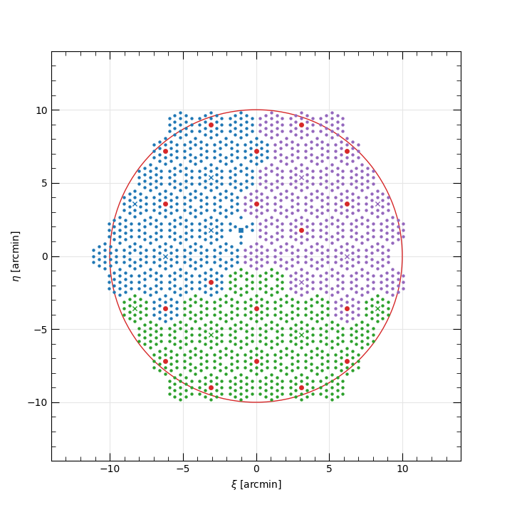
We’re currently assessing these options.